Background
Hans wanted to learn how to program microprocessors. Therefore he took a 7,5 hp PIC programming course at the Royal Institute of Technology (KTH) in Stockholm. [ IL131V Tillämpad digitalteknik med PIC-processor ]  Application
His plan was to build a DCF77 Simulator.
2010-01-09 Initial description
2010-02-07 Begäran om programmeringsuppgift
Requirement specification
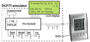
DCF77 is the German long-wave transmitter that provides correct time to radio-controlled clocks in the northern part of Europe. The transmitter sends time data on 77.5 kHz according to a public protocol. The DCF77 simulator should be able to create a puls signal identical to DCF77 but with selectable time, date and other parametrers. In other words, be able to create a false time.
The simulator should have a display that shows the data of the transmission in various views to demonstrate the DCF77 protocol.
By connecting the simulator to a radio-controlled clock, the function can be verified.
The acronym DCF77 stands for:
D=Deutschland (Germany)
C=Long wave signal
F=Frankfurt
77=Frequency: 77.5 kHz.
The DCF77 public protocol (in Swedish).
Exempelvärden för 2017-12-24, 21:05, DST=0, söndag
| Bit | Symbol | Exempel | Beskrivning |
|---|---|---|---|
| 0 | M | 0 | Start av minut, alltid 0 |
| 1‑14 | väder | 0110... | Väder-information från Meteo, mm |
| 15 | R | 0 | Indikering av onormal sändning, normalt 0 |
| 16 | A1 | 0 | Annonsering av sommartid (DST), sätts till "1" timmen före ändring. |
| 17‑18 | Z1, Z2 | 0 1 |
01 = normaltid 10 = sommartid |
| 19 | A2 | 0 | Annonsering av skottsekund, sätts till "1" timmen före ändring |
| 20 | S | 1 | Indikering av start på tidinformation, alltid"1". |
| 21‑27 | minuter | 1 0 1 0 0 0 0 |
Minuter 00-59 som BCD, 7 bitar, lsb först [ 1-2-4-8 | 10-20-40-xx ] |
| 28 | P1 | 0 | Paritetsbit, jämn paritet över bit 21-28 |
| 29‑34 | timmar | 1 0 0 0 0 1 |
Timmar 00-23 som BCD, 6 bitar, lsb först [ 1-2-4-8 | 10-20-xx-xx ] |
| 35 | P2 | 1 | Paritetsbit, jämn paritet över bit 29-35 |
| 36‑41 | dag | 0 0 1 0 0 1 |
Dag 01-31 som BCD, 6 bitar, lsb först [ 1-2-4-8 | 10-20-xx-xx ] |
| 42‑44 | veckodag | 1 1 1 |
Veckodag som BCD, 3 bitar, lsb först [ 1-2-4-x ] 1 = måndag |
| 45‑49 | månad | 0 1 0 0 1 |
Månad 01-12 som BCD, 5 bitar, lsb först [ 1-2-4-8 | 10-xx-xx-xx ] |
| 50‑57 | år | 1 1 1 0 1 0 0 0 |
År 00-99 som BCD, 8 bitar, lsb först [ 1-2-4-8 | 10-20-40-80 ] Århundradet "20" är undersförstått. |
| 58 | P3 | 1 | Paritetsbit, jämn paritet över bit 36-58 |
| 59 | - | - | Markering av ny minut, ingen puls |
A simulator and demonstrator
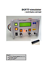
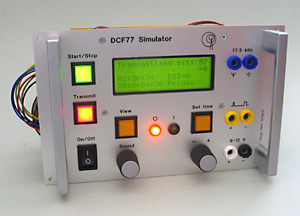
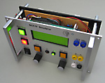
The DCF77 Simulator is a combined simulator and demonstrator. It generates DCF77 time code at the same time as it displays the code in different views. The time code to be generated can be set to any time between 2000-01-01 and 2099-12-31.
The simulator can control DCF clocks via two interfaces:
- Electrical
- Radio-signal via a built in low-power transmitter

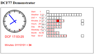
Demonstrator web app
Hans makes a web app in Javascript that shows the coding.
It is not finished.
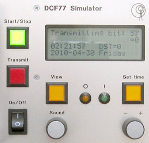
The controls
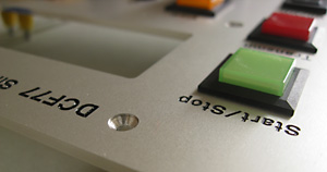
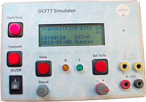
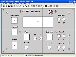
Start/Stop: Starts and stops the time signal according to the DCF77 protocol and the set time.
Transmit: Switches the transmitter on/off. Can only be activated when signal generation is in progress.
View: Switches between 4 different viewing modes:
a) Shows the set time and transmitted bit value, without LCD background light
b)
Shows the set time and transmitted bit value, with LCD background light
c) Shows an overview of all 60 bit values for a complete minute interval, where the current bit is underlined
d) Shows a dynamic explanation of the bit information currently sent.
Set time and -/+ dial: Activates setting mode where the time can be set using the -/+ dial. The time parameters are sequentially stepped through: Hour, Minute, Second, DST, Year, Month, Day, Weekday. The set time is finally stored in EEPROM.
Sound: Activates a audio indication to complement the text display. The dial is a normal volume control. In addition, it controls the sound types. By quickly turning the knob up+down, 5 different sound types are stepped through:
a) No sound, amplifier off.
b) Click sound. c) Tone sound. d) Tone sound inverted, high frequency. e) Tone sound inverted, low frequency.
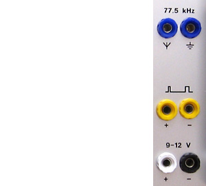
The external connections
77.5 kHz: Connection to external antenna, if required.
Pulse: Pulse interface for electrical connection to a DCF clock. The signal simulates the output from a DCF77 receiver.
9-12 V: External power supply, if required.
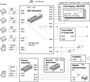
Block diagram
The simulator is built around a PIC-processor for the DCF77 simulation and control. In addition the following modules are included:
- Radio interface with a low power test transmitter 77.5 kHz
- 4×20 characters LCD display
- Two support processors for sound selection and sound generation
- Audio amplifier with digital potentiometer
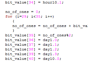
Program code
The code is written in the programming language C, for the B Knudsen Cc5x C-compiler - not ANSI-C.
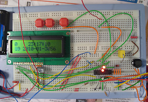
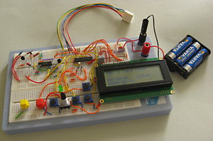
The 1:st prototype
The DCF77 simulator was first designed with PIC16F628, a two-row LCD display and an electrical interface to the clocks.
 2010-02-07_prototype_pic16f628.c
Hans writes a specification in Swedish:
Hårdvara
Microprocessor PIC16F628 med följande interface:
   Utgångar:   1 för puls, att koppla till extern
                 radiostyrd klocka.
               1 för eventuell högtalare/buzzer.
               1 för eventuell LED-indikering.
               6 för LCD display 4×20 tecken, ASCII.
   Ingångar:   4 för tryckknappar.
   Oscillator: 2 för kristall 32,768 kHz med tillhörande
                 kondensatorer för en stabil 1 Hz signal.
                    ________  ________
                   |        \/        |
          LCD.D6 <-|RA2   16F628   RA1|-> LCD.D5
          LCD.D7 <-|RA3            RA0|-> LCD.D4
         Btn SET <-|RA4-od    RA7/OSC1|-> Btn INC
     Loudspeaker <-|RA5/MCLR  RA6/OSC2|-> Btn MODE
             GND --|Vss            Vdd|-- +5V
       Pulse out <-|RB0/INT  (RB7)/PGD|-- XTAL
             LED <-|RB1/Rx   (RB6)/PGC|-- XTAL
       Btn START <-|RB2/Tx         RB5|-> LCD.RS
          LCD.EN <-|RB3/CCP  (RB4)/PGM|-- 1k- Gnd
                   |__________________|

Mjukvara
Programmet ska skrivas i C och kompileras med
B. Knudsens C-kompilator Cc5x.
The 2:nd prototype
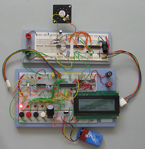
After upgrading to PIC16F690 a rotary encoder could be used for setting time. In addition, a 4-row LCD display with several "views" could be utilized thanks to the larger program memory.
The 3:rd prototype
The final simulator design added sound to emphasize the "display" of the time signal. A rotary encoder is used for both volume control and for selecting sound type.
This final version uses PIC16F886 as the main processor with the two previously used processors as support processors taking care of the sound selection and generation.
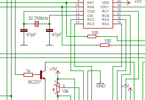
Circuit diagram
Besides the 3 PIC controllers the circuit also uses an amplifier, a digital potentiometer and a MOS-FET relay.
Eagle schematics file:
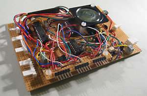
Circuit board
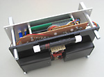
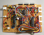
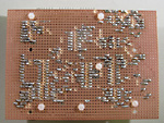
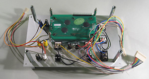
The simulator is built on a strip-board, also known as Veroboard. The board also holds the loudspeaker.
Besides pin connectors to the front panel controls, battery and antenna there are also 3 pin connectors for in-circuit programming (ICSP™) of the three PIC controllers on the board. The PICkit™; 2 programmer can be plugged in directly onto the connectors.
Front panel
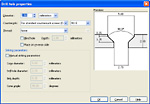
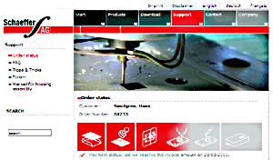
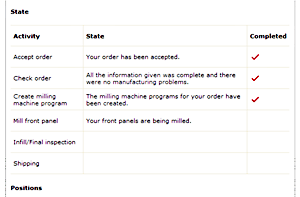
The front panel was drawn in Front Panel Designer and sent to Schaeffer AG for milling and engraving. About Front Panel Designer
Front Panel Designer file:  dcf77_simulator_frontpanel.fpd
The PIC processor
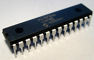
To be able to control all push-buttons and rotary encoders and to display the DCF protocol in different views, the PIC16F886 was required. The processor was purchased from Kjell & Company in Västerås during a lunch break for SEK 49. This little chip includes:
- 8 kBytes program memory for code
- 368 Bytes RAM memory for storing variables
- 256 Bytes EEPROM for storing data
- Internal clock oscillator 8 MHz
- 24 Input/outputs

Synchronisation test
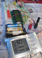
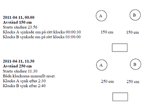
Hans test the simulator with 2 radio-controlled clocks, one large analog wall clock and one small digital alarm clock.
The tests are made at distances from 0.6 to 2.5 meter.
Test with radio receiver
Hans visits a radio amateur; Ragge Jagero in Sala, and listens to the signal transmitted by the simulator.
Lecture for radio amateurs
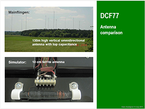
Hans makes a presentation of the project at a monthly meeting in Västerås Radioklubb.
Other designs: Greece
 2012 January: Based on the information on this web page other people have succeeded building the simulator, with smaller or larger personal adjustments. One of them is Nick Raptis from Greece. Extracts from Nicks report 2012-01-24 published with his permission:
| … I'm an electronics engineer living in Athens, Greece and the reception of DCF-77 signal is rather pure as I suppose is, also, the case in certain parts of Sweden. Especially in my lab, I had no success to receive it and even less luck to test or troubleshoot any circuits designed to use this signal.
I found your site almost after you published this circuit, during summer 2010, and started gathering all necessary components. Unfortunately, I got lazy during the process and left this project behind although not forgetting about it. During last Christmas holiday period I pulled myself together and started building it. I used almost the same method as you did, by point-to-point wiring. The first tests with the main signal generating microprocessor were successfull and I continued to the end. Although, I didn't follow your method of the very professional front panel construction, my approach was quite good looking and generally acceptable. Even more, I have enriched my electronics lab with a trustful DCF-77 signal generator ready for any upcoming project. Just for your knowledge, as I could not find anywhere the 77,5 kHz crystal and the antenna required (my father could not help me as yours did!!), I ripped these components from a Conrad DCF-77 receiver module. … |
Other designs: Sri Lanka
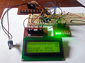
 2013 August: Pasan built the simulator on experimental board and had plans to do an SMD variant.
Programs used
Hans used several programs to develop and program the simulator.
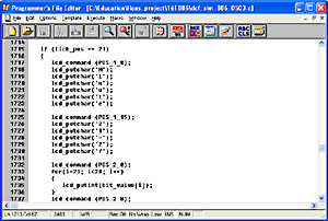
Programmer's File Editor 1.01
The program code was written with PFE. The text editor requires no installation, as it is run as an exe-file.

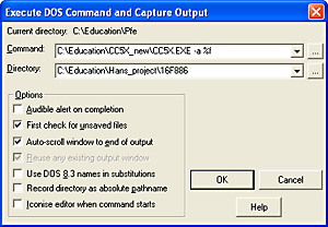
Compiler CC5X 3.4
The C-code was compiled with CC5X C Compiler for the PICmicro Devices (B Knudsen).

Eagle 5.7.0 Light
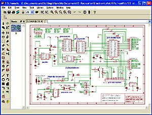
The circuit diagram was drawn in Eagle. The program is an easy to use drawing tool with the possibility to define your own components.

Front Panel Designer 4.0
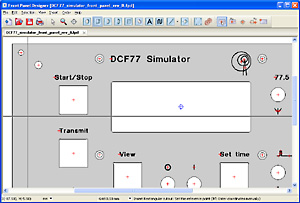
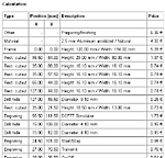
The front panel was designed with the Front Panel Designer. It is possible to make cut-outs in different shapes and specify engraving with different styles and sizes. A menu command Pricing presents a detailed price specification. When the design is ready, the order is sent to Schaeffer AG in Germany by some clicks. After some weeks the front panel is delivered, exactly as drawn.
Hans writes an article about how to create nice front panels (in Swedish): Byggtips: Snygga frontpaneler


Inlämningsuppgifter
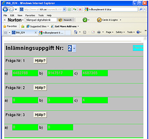
Förutom laborationsövningen så ingår inlämningsuppgifter. Dessa kan man lösa hemma och svara via webbformlär.
Foto-information
Fotograf
Hans Sundgren, om inte annat anges.

