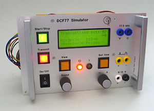
DCF77 Simulator
Description: A combined simulator and demonstrator of the DCF77 system used for setting time of radio-controlled clocks. The time setting protocol is demonstrated by light, text and sound.
Challenges: The first PIC-project designed by Hans. Three different PIC-processors were used in the end. One rotary encoder is used for both setting volume and selecting sound type.
Ready: 2010
More information: DCF77 Simulator

ARDF sound transmitter
Description: An ARDF transmitter with voice identification. The timer transmits any recorded sound message at a set interval on 144 MHz. The designed is using the SquawkBox transmitter circuit from Doppler DF Instruments Bob Simmons.
Design challenges: Robust construction and small size. Adapted for connection to an existing VHF transceiver for higher power output.
Ready: 200X.
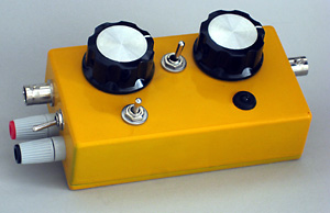

Automatic decision maker
Description: A random yes/no generator.
Design challenges: Small size, adapted for mass production and a single pushbutton for on/off/start which means an auto power off function.
Ready: 1994.

Meeting cost counter, compact
Description: A small pocket size version of the meeting cost counter.
Design challenges: Putting it all together in a small box including thumb wheel switches for setting the rate. By using an LCD display with integrated counter it was quite easy to design the unit.
Ready: 1992.

Meeting cost counter
Description: A measurement tool for meetings. By multiplying the number of persons and average hourly rate you get a cost per hour. Enter this rate on the slider and press the start button. The display will then start to count the accumulated cost. This means that you can say to a person: "John, you can speak for 10 dollars now." Today there are software based Meeting Meeters™ but this one was made before the computers were common.
Design challenges: Everything on one board, no enclosure.
Ready: 1990.
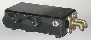
Touch controlled morse keyer
Description: Touch sensitive keyer without mechanical switches. Based on a combination of Curtis Keyer 8044 chip and a proximity switch circuit.
Design challenges: Compact unit with all circuits including batteries. Mechanical design of "paddles" using two wall hooks for clothes.
Ready: 1990.


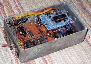
Thank-you-blinker with integrated music horn
Description: Originally a music horn for the car expanded with a thank-you-blinker.
Design challenges: Robust construction to be able to withstand the vibration and high temperature in the engine compartment of the VW Golf. As few cables as possible to simplify the retro-fit in a new car. SCART-contact was used for the multi-conductor cable between the engine compartment and the dashboard with rocker switches and thumbwheel switches.
Ready: 1989.
End-of-life: 1999. Removed from the car and scrapped.
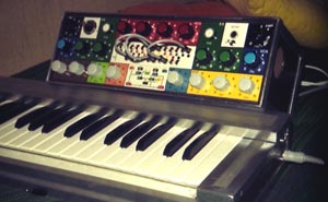
Music synthesizer
Description: Building a music synthesizer from a kit from USA. The circuit board was bought from USA but the mechanical design was developed by Hans. The project was documented as a part of a special project in the high school Berzeliusskolan in Linköping.
Challenges: The mechanical design using a separate main unit and a full size keyboard. Describe the design of the synthesizer.
Ready: 1976
End-of-life: 19xx. The synthesizer was sold to a private person.
Description, 11 pages, in Swedish

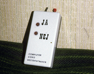
Decision maker
Description: Hans named this item a computer aided decision maker. He designed it himself.
Challenges: Making it true random.
Ready: 1975
End-of-life: The device is scrapped around 1980.
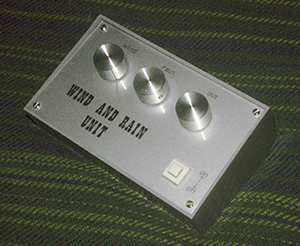
Wind and rain generator
Description: A kit bought from Great Britain and enclosed in a box of own design.
Challenges: Mechanical design.
Ready: 1975
End-of-life: The device is scrapped around 1980.
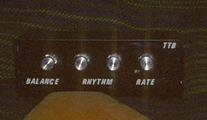
Drum machine
Description: A kit bought from Great Britain and enclosed in a box of own design.
Challenges: Mechanical design.
Ready: 1975
End-of-life: The device is scrapped around 1980.
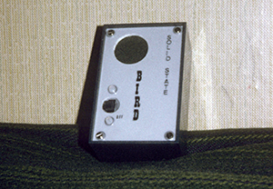
Solid state bird
Description: A kit bought from Great Britain and enclosed in a box of own design.
Challenges: Mechanical design.
Ready: 1975
End-of-life: The device is scrapped around 1980.
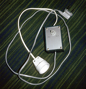
Dimmer
Description: A home built dimmer for 230 V AC with only 2 positions: Full or half.
Challenges: Avoid electric shock during construction.
Ready: 1975
End-of-life: The device is scrapped around 1980.
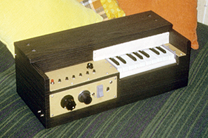
Mini-organ
Description: The magazine Radio & Television, October 1970, described the cirucit of an electronic mini-organ "Kompis". It was first mentioned in Radio & Television, September 1969. Hans read about it in 1972, built it and finished it 1973.
Challenges: Mechanical design of keyboard, using a childrens piano.
Ready: 1973
End-of-life: Around 1980. The organ was scrapped.
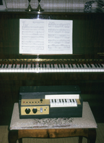
Utdrag ur Hans' dagboksanteckningar januari-april 1979.
Köpt apparatlåda och omkopplare på Eltema 8:90 kronor. Var i Norrköpings mässhallar och såg "Båtar-73".
Fick orgeln att låta lite grann.
Var på extraslöjden. Håller på att skruva ihop orgellådan. Åkt hem till Jan F och lånade noter till Mendelssohns bröllopsmarsch.
Pelle och Biggan här.
Hade 2-timmars svenska-prov. Fick reda på matte-standardproven. Hade under medel.
Spacklade orgel-lådan på extraslöjden.
Tidningar huvudbiblioteket går ut.
Sista gången i extraslöjden. Tog hem orgellådan. Lånade en bok på biblioteket. Lade mig 23:30 efter TV.
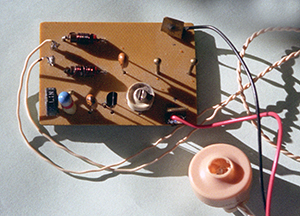
FM-transmitter, home-built
Description: Hans build a transmitter with inspiration from some circuit diagram he find.
Challenges: Try to extend the transmission range.
Ready: 1973
End-of-life: In July 2001 the transmitter is sent to Limmareds Radio as part of a campain. Hans buys a new amateur radio transceiver and for every transmitter he sends in, he gets a discount.

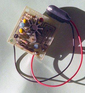
FM-transmitter, kit
Description: Hans buys a transmitter kit from the company JostyKit 1973-01-04 for SEK 21.
Challenges: Try to extend the transmission range.
Ready: 1973
End-of-life: In July 2001 the transmitter is sent to Limmareds Radio as part of a campain. Hans buys a new amateur radio transceiver and for every transmitter he sends in, he gets a discount.

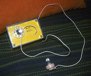
Crystal radio
Description: Hans buys a crystal radio kit from the company JostyKit 1973-01-04 for SEK 21. He builds it and puts it in a box of his own design.
Challenges: Front panel.
Ready: 1973
End-of-life: Around 1978. The radio is scrapped.
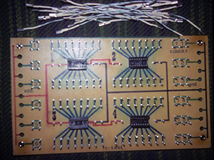
Solderless breadboard
Description: Hans likes to play around with the new TTL logical circuits. In order quickly test different circuits he builds a "breadboard" with socket for ICs and jumper wire connection points.
Challenges: Etching the circuit board.
Ready: 1972
End-of-life: Around 1978. The unit is scrapped.
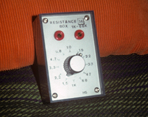
Resistance box
Description: Hans builds a resistance box in order to quickly test different values of resistances. The range is 1–68 kohm.
Challenges: Mechanical design.
Ready: 1972
End-of-life: Around 1978. The unit is scrapped.

Handheld sounder
Description: An electric bell controlled by a push-button. The design was based on components bought from Clas Olsson and what was available in Hans' father's hobby room.
Challenges: Small hand-held unit with all components integrated; electric bell, push-button and batteries in a wooden box.
Ready: 1964
End-of-life: 1968. The device is too simple to be kept and is scrapped.


